
What Should a Hydraulic Power Unit Tell a Machine?
A hydraulic power unit should communicate more than whether it is running. It should provide the pressure, fluid level, temperature, and filtration information the machine needs to support operation, identify potential problems, and respond when conditions fall outside defined limits. The challenge is deciding which information matters—and how the machine should use it.
That requires more than adding sensors to a hydraulic circuit. It requires integration between the hydraulic design, control system, operator interface, and service strategy.
At GS Global Resources, mechanical and controls engineers work together to connect those decisions. Hydraulic requirements inform sensor selection, controller capabilities shape how signals are collected, and the OEM’s operating and service needs determine how that information is displayed and acted upon. The result is a coordinated approach to hydraulic power unit design—not separate hydraulic and controls decisions left for the OEM to reconcile.
For engineers designing industrial equipment or heavy machinery, the starting question is straightforward: What does the machine need to know about its hydraulic power unit to operate as intended, protect its components, and make troubleshooting more efficient?
Which Hydraulic Power Unit Conditions Should a Machine Monitor?
The right monitoring strategy depends on the machine’s hydraulic functions, control architecture, service requirements, and operating risks. There are several key conditions to consider: system and work-function pressure, reservoir fluid level, fluid temperature, filter differential pressure, and fluid cleanliness.
Each measurement should serve a defined purpose.
| Condition | What it tells the machine | How the information can be used |
| System pressure | Whether hydraulic supply pressure meets the expected operating condition | Help narrow the starting point for troubleshooting |
| Work-function pressure | What pressure is available at a monitored machine function | Identify changes in function performance and compare them with system pressure |
| Reservoir fluid level | Whether fluid has reached a low-level threshold or how much remains | Warn of low fluid and support protective responses |
| Fluid temperature | Whether the hydraulic fluid is approaching or exceeding a defined temperature limit | Trigger warnings or stop operation when required |
| Filter differential pressure | The pressure difference across the filter | Provide maintenance warnings and identify when filter service is needed |
| Fluid cleanliness | The contamination level represented by an ISO cleanliness code | Verify cleanliness against component requirements and inform protective responses |
These are design considerations, not a universal instrumentation package. The final sensor selection and response logic must reflect the application.
Choose Between Switches and Transmitters Based on the Information Needed
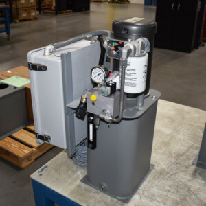
One early integration decision is whether the controller needs a threshold indication or a continuously measured value.
For example, a level switch can indicate that reservoir fluid has reached a certain low-level threshold while a level transmitter provides an actual, specific measured level. The same distinction applies to filter monitoring: a switch can signal a service condition, while a differential pressure transmitter can show the pressure difference as it approaches a maintenance threshold.
That additional visibility can help an OEM distinguish between “service will be needed soon” and “service is needed now.”
However, sensor selection cannot happen independently of the control system.
Controller I/O Can Determine What the HPU Communicates
Available controller inputs often influence whether a design uses switches or transmitters. For example, if a controller has four available analog inputs and the design requires four pressure measurements, those inputs are already allocated. Measuring reservoir level or filter differential pressure through additional analog signals would require a change in the control architecture. Otherwise, threshold switches may be the appropriate choice for those conditions.
This is why the hydraulic schematic and controller input/output (I/O) plan need to develop together. The engineering question is not simply, “Which sensor should we install?” It is:
- What decision must the machine make?
- Does that decision require a measured value or a threshold signal?
- Can the selected controller receive the signal?
- What should happen when the condition changes?
More Focused Machine Troubleshooting
Pressure measurements become more useful when engineers consider how they relate to one another.
For example, if a work function loses pressure while system pressure remains at its expected level, that points the investigation toward the function’s valve or a downstream circuit. If system pressure also drops unexpectedly, you need to investigate the hydraulic supply.
All of this information gives you a starting point—not a definitive diagnosis. The objective with HPU integration is to make those relevant readings accessible so technicians can begin with evidence rather than searching the entire hydraulic system.
Define What Happens After an Alarm
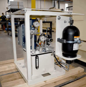
Installing a sensor does not complete the protection strategy. The control system also needs a defined response to the condition being monitored.
In certain cases, it may be appropriate to completely stop operation, but under other conditions reduced performance may be the appropriate response. For example, low reservoir level and high fluid temperature are conditions that can warrant stopping operation because of the potential for pump damage, cavitation, or seal damage. Conversely, filter service indications or certain low-pressure conditions may instead prompt reduced performance, depending on the application.
The important distinction is that these responses must be engineered for the machine. For each monitored condition, the OEM and integration team should establish:
- When to notify the operator.
- When to request maintenance.
- Whether reduced performance is appropriate.
- When operation must stop.
This connects hydraulic measurements to actual machine behavior rather than leaving them as isolated values on a display.
Start With the Hydraulic Requirements—and the Information Behind Them
Specifying a hydraulic power unit means defining more than pressure and flow. It also means determining what the machine needs to monitor, how the controller will receive that information, and what operators and technicians need to see.
GS Global Resources brings mechanical and controls engineering together to work through those requirements with OEMs. From sensor selection and controller I/O to diagnostic access and machine responses, those decisions need to be developed as connected parts of the system, and our team has decades of experience seamlessly integrating both of elements.
Tell Us About Your Hydraulic Power Unit Needs
Whether you have detailed specifications or are still defining the application, share your HPU requirements with GS Global Resources to get personalized feedback from our engineers and start a conversation about your power unit.